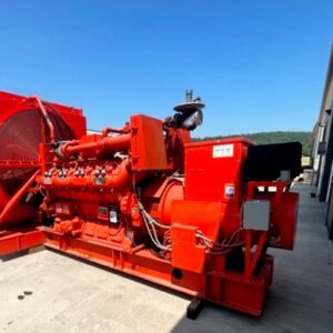
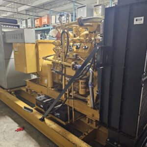
700KW Waukesha Gas Generator
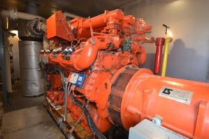
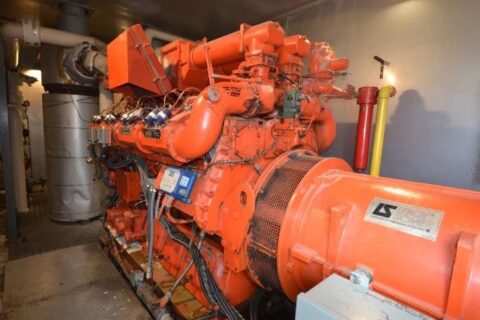
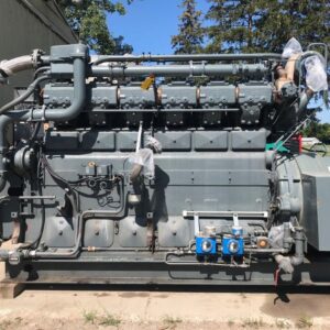
700KW Waukesha Gas Generator, Natural Gas Cogeneration Power Plant. Model VGF P48GL, 1800 rpm, 600 volt, 60 HZ, 16 test hours since overhaul by OEM. Two Sound Enclosured Buildings with Heat Recovery System. Equipped with Air Handling Module, Circulation Fans, Circulation Pumps, Cooling System, Control System, Utility Grade Synchronizing Panels, Air System, Fuel System, Exhaust System, Batteries, Batteries chargers, Generator package consists of two Sound Enclosures. Excellent Condition, Complete package
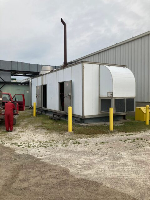
The 700 KW Waukesha VGF P48GL Gas Cogeneration Power Plant is of modular design. Power package consists (2) Sound Attenuated Containerized Enclosures. This provides easy and quick setup and allows the plant to operate in residential and commercial areas.
The VGF Series is top of the line in Waukesha high performance engines. It provides Fuel Flexibility, Reliability and Robust Performance. The P48GL is a cleaner burning engine and offers a long duration between maintenance intervals.
Waukesha P48G generator package 700 KW Continuous Duty, 600 volt, 1800 rpm, 60 HZ and is equipped with a Heavy Duty Leroy Somer Generator. The Waukesha P48GL gas generator package has been overhauled by OEM and has 16 test hours. since overhaul, the generator has been maintained in accordance with OEM preservation guidelines.
Power Package consists of Jacket and Exhaust Heat Recovery System, Separate Air Handling Module, Circulation Fans, Circulation Pumps, Cooling System, Control System, Utility Grade Synchronizing Panels, All Equipment is housed in Sound Attenuated Enclosed Trailers.
Once on site, the package can generate immediate power. Great Package for the Oil Patch, Industrial Manufacturing, Production Facilities, Data Centers, Health Facilities, Off the Grid Locations and much more.
Plant Configuration
The plant consists of two sound enclosures. The first container is an oversized container (white) with lifting lugs that house the ICE–GS and the controls. The second container (green) houses the cooling unit. The cooling unit is relatively light and consists of a set of intake louvers on one end that brings in outside air or return air from the building. The air then passes through a bank of fabric filters.
Once through the filters the air then moves through the fan room, which houses a 40 HP motor that drives the 2 fan units with one common shaft. Air then passes through the radiator that is connected to one of the cooling loops. The air is discharged to another set of louvers, which would either direct the heat to the outside or to the building depending on requirements. The second cooling loop had previously serviced another portion of the building and has been removed. The two containers are connected by the two cooling loops and the associated electrical and control wiring system.
